DC Voltage Sensing Hardware
Voltage sensing of the DC input ($V_{DC}$) is achieved through a simple resistive divider. The resistive divider is made up of a limiting current resistor ($R_{limit}$) paired with a sensing resistor ($R_{sense}$). The voltage across the sensing resistance is measured by an ATMEGA328P analog pin which senses a voltage in the range of 0-5V ($V_{sense}$). It should be noted that the ATMEGA328P I/O pins cannot exceed 5V, as doing so may result in permanent damage to the MCU.
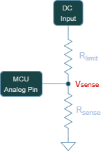
Resistors values are chosen based on this condition as well as drawing an insignificant amount of power from the DC input, since the current in this path is to be delivered primarily to the output load.
The resistor values of $R_{limit} = 120k\Omega$ and $R_{sense} = 10k\Omega$ were chosen based on the standard voltage divider equation:
\[V_{sense} = V_{DC} \times \left( \frac{R_{sense}}{R_{sense}\times R_{limit}} \right)\]Given that the nominal DC input range is 12V to 48V, this translates to a sensed voltage as low as 0.92V and a high as 3.69V. It is evident that the full scale range of the analog pin is not used (0-5V), but this is intentional to account for potential overvoltage driving at the DC pin. Nonetheless, the 10 bit analog to digital converter (ADC) of the ATMEGA328P works as necessary in detecting the DC voltage based on the design parameters selected.